Wiring
As promised and also the main reason why I have yet to updated my build in a few months is I have been wiring and documenting the wiring on my 818. My goal was to wire up and get the car to run before I updated anything else. I am running a 2002 STI EJ207 Engine and ECU with a 2003 WRX harness. I deleted a lot of things and made a stand alone harness. My cars ODB2 port and ECU work correct, and all the engine sensors are happy.
Note: I am running an Infinity Box so I am only running the engine with OEM wires. Lights, gauges, OEM fuses, and the OEM Relays are all deleted. You may need to keep a few more wire,relays, and fuses if you plan to not use an infinity box. This guide should still help. The main thing you will need if your not going to use an infinity box is the main relay, Both fuse boxes(or make a smaller one), and the ignition relay. Again this is an engine only harness, if you follow this guide and don’t use an infinity box you will still need to wire your own body harness for things like lights, signals, wipers, horn, etc.
I have successful started the car and ran it with only a check engine lights for the rear O2 sensor and VSS sensor I had deleted.
If there is anything you guys feel I need to be more clear on please let me know and I will make sure to fix things.
Rather the reinvent the wheel with wiring diagrams I have edited the OEM diagrams and will explain each page as we go. The engine harness is all you need the rest of the lights, switches, and other optional things are all deleted. After you have gutted the harness you will only have engine plugs and sensors remaining. Goodbye OEM wiring: ABS, A/C, horn, cruise control, security, lighting, switches, relays, airbags, etc.
If you need help to find what each connector looks like I found this to be the most helpful Mechie3’s wiring guide.
Page 1:
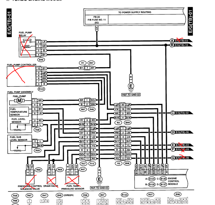
- Fuel Pump Relay
- LR:
- Power from Main relay
- This line is not needed since power is drawn from the infinity box straight to the pump controller.
- GR:
- Signal wire for pump relay and goes to page 10 which ends up connecting to Ignition coil
- Im running a DCCD fuel pro so I am running the GR wire from the ecu & IG coil to the fuel positive on the DCCD fuelpro. This also works as the inline fuse that’s called for in the top since it uses the Infinity box fuse.
- B:
- Not needed
- BY:
- Not needed if your running a DCCD fuel pro.
- LR:
- Fuel Pump controller (https://www.dccdpro.com/product/fuelpro/)
Note: I’m running a DCCD fuel pro since I have a Walbro 450 pump.- VW:
- ECU demand signal. This wire is needed for the DCCD pro ECU pin.
- LgR:
- Wire is just a 12V line to inform ECU the controller is alive. Connect to DCCD fuel pro with the GR(pump relay) line and Infinity box power line.
- BW:
- Connect the DCCD Pro supply Negative/ground line. This is the ground to the pump
- I removed this line altogether and used the wire directly from the pump connector so I had a B color wire to my DCCD fuel pro.
- BOr
- Connect to DCCD Pro Positive Supply line. This is the power for the pump
- I removed this line altogether and used the wire directly from the pump connector so I had a BR color wire to my DCCD fuel pro.
- BY
- Deleted since I have no fuel pump relay.
- B
- Deleted. But you will still need some kind of ground wire for your DCCD fuel pro.
- VW:
- Fuel Pump Assembly R58
- Fuel pump
- BR:
- Connect to DCCD fuel pro supply positive
- B
- Connect to DCCD fuel pro supply negative.
- BR:
- Fuel Temp/Fuel Level
- Keep the same.
- Fuel pump
- Fuel Level sub r59
- Keep the same
Everything else can be kept or removed. I deleted everything else in red. Make sure to remove any unused wires from the ECU.
Page 2
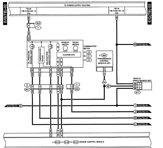
VSS may be needed some have reported no problems other people have. I needed it but I used a MapDCCD wheel speed sensor kit which uses the ABS sensors to read speed. I taped that into the GY wire on the ECU.
I am running an after market gauge cluster so I have eliminated most of the wires here but the tach, fuel level, and check engine light wires. Everything else can be removed.
Page 3
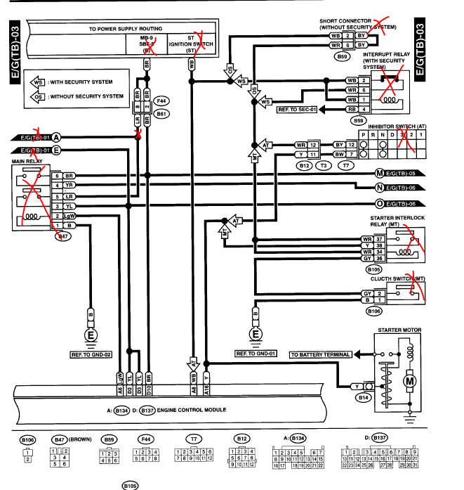
- Main relay (deleted with Infinity Box)
- BR:
- Power to ECU and ODB2 port.
- Power connect to the infinity box power.
- YR
- Front and rear O2 sensor power
- I deleted the rear. EJ207 only needs to front sensor for A/F readings
- Connect to the BR line.
- LR
- Delete
- Powers pump but is no longer needed since Infinity box has its own power line.
- YL
- Power to ECU, Waist Gate, MAF, Injectors, Purge control, IAC.
- Connect to BR & YR lines. (So BR, YR, YL should all be powered from the infinity box main relay power wire)
- Power to ECU, Waist Gate, MAF, Injectors, Purge control, IAC.
- LgW
- Delete
- B
- Delete
- BR:
- Starter
- Y
- Connect the ECU and starts Y wire to the starter wiring of the infinity box.
- Y
The rest can be deleted everything else is security and AT stuff.
————————————————————————————-
Page 4
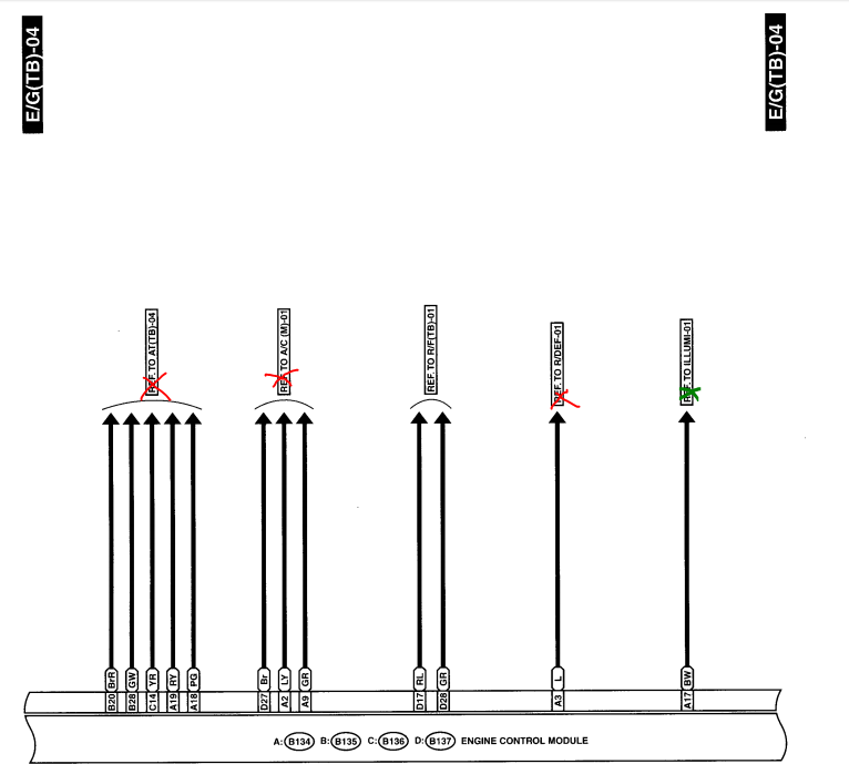
Remove everything but the R/F wires these are for your radiator fans.
————————————————————————————-
Page 5
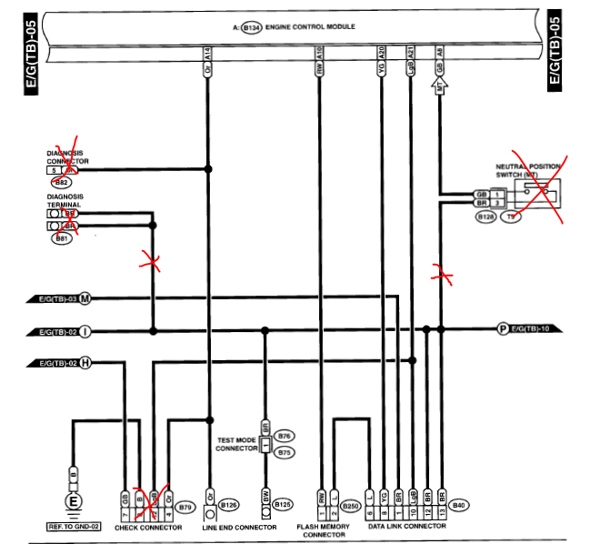
- B82 diag
- Subaru only diag tool not needed.
- B81 diag
- Subaru only diag tool not needed.
- Only remove the wires do not remove the whole BR line just remove to the connecting point.
- Check Connector
- Subaru only diag tool not needed.
- GB
- Connects to VSS but is not needed for VSS to function.
- Delete
- Connects to VSS but is not needed for VSS to function.
- B
- Delete
- LgB
- Delete up tell you get to the connecting point.
- Or
- Delete up tell you get to the connecting point.
- GB
- Subaru only diag tool not needed.
- Natural position
- Delete up to connecting point. FYI I have a JDM ecu and it didn’t require me to bridge the connection you may need to if your using a USDM wrx ECU/ EJ205.
Keep the rest
————————————————————————————-
Page 6
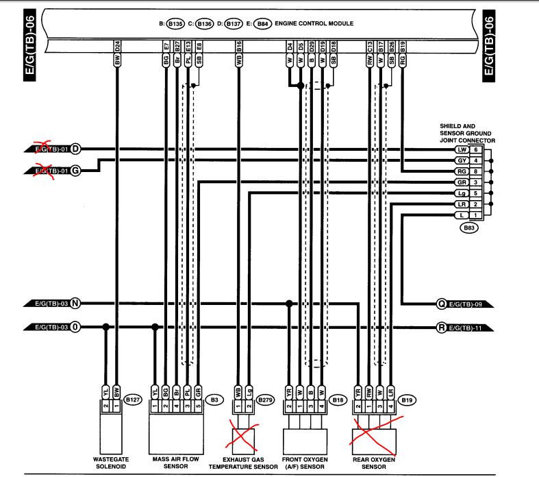
Straight forward remove the red if you don’t want these sensors I had no need for them. Keep the rest as is.
————————————————————————————-
Page 7
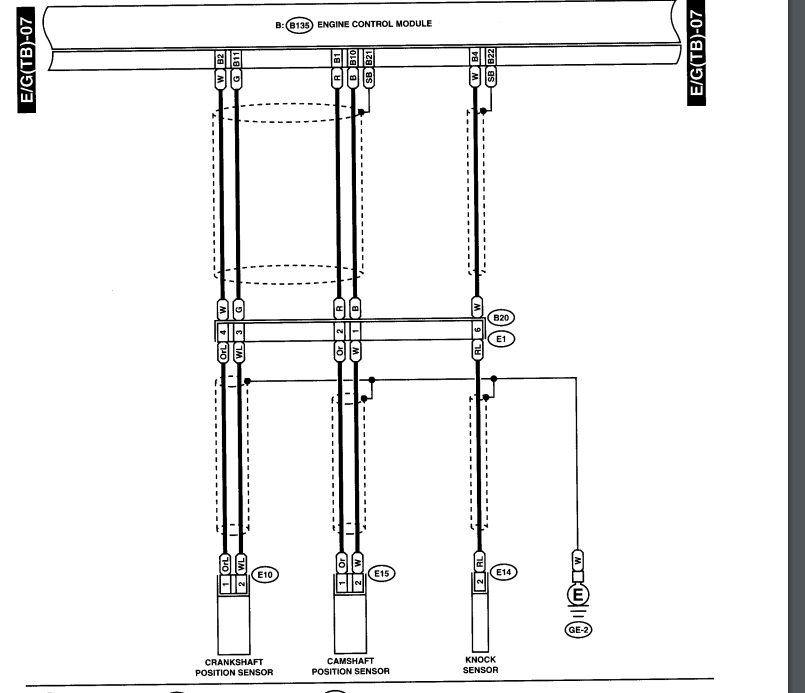
Nothing needs to change unless you have a EJ207 see below if you do.
EJ207:
You will need to repin the wiring connectors to work with the Ej207 engine harness. See the image below for the new pin locations.
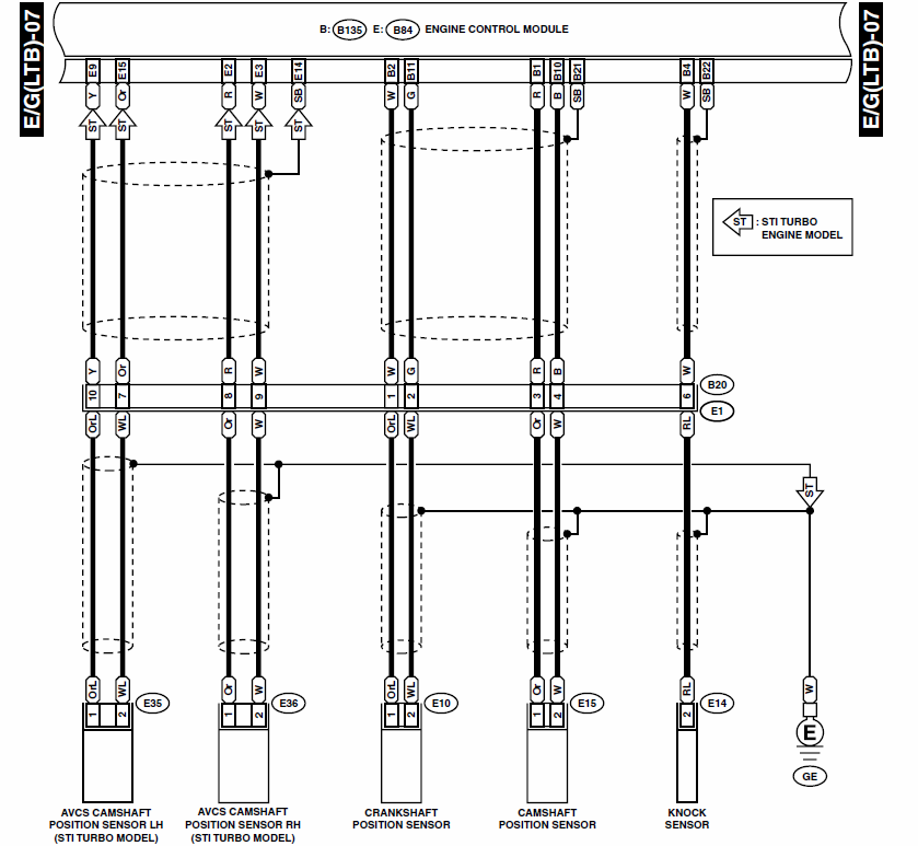
The AVCS wires will need to be shielded wire. I used security wire from ACE. You can get the pins in bulk or shoot me a PM and I can send you some pins for less then anyone else. For more see my other thread about ECU pins. http://thefactoryfiveforum.com/showt…Wire-terminals
————————————————————————————-
Page 8
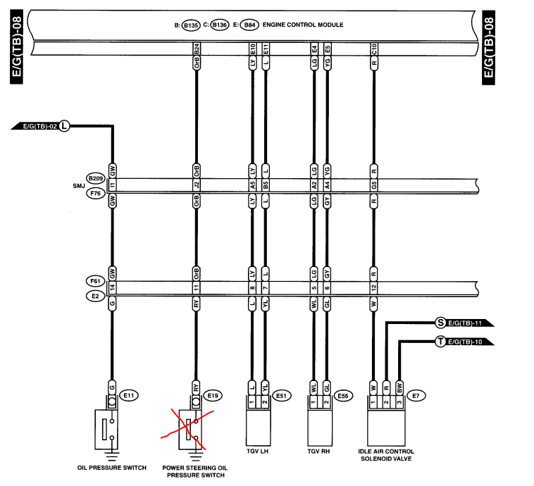
- Remove power steering light
- Some delete TGV thats up to you. If you have a EJ207 You can remove all the TGV wires as they wont be used.
————————————————————————————-
Page 9
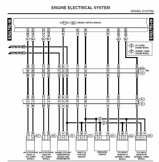
- Nothing changes here. You can remove the TGVs if you like.
- For the EJ207 you will need to pin your harness to match the diagram above follow the ST arrows.
————————————————————————————-
Page 10
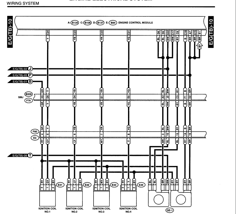
No changes
————————————————————————————-
Page 11
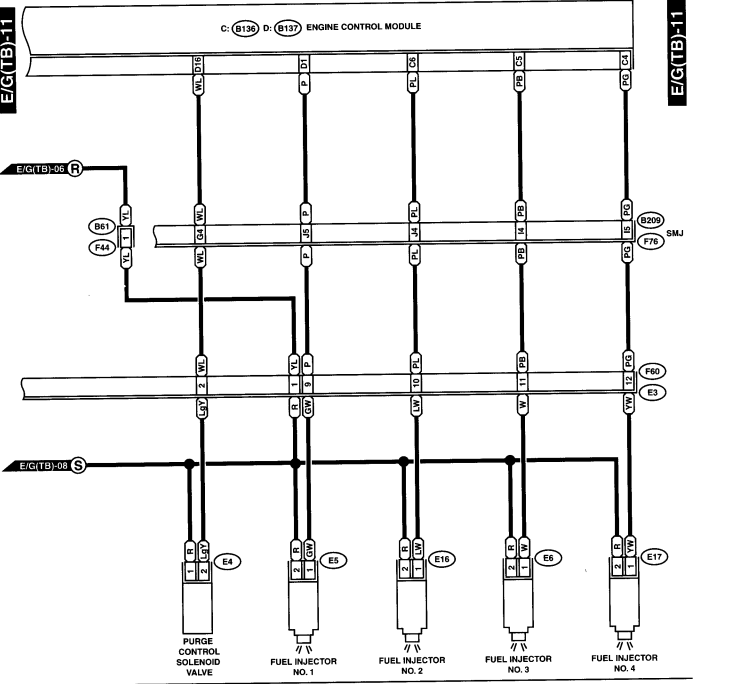
No changes
————————————————————————————-
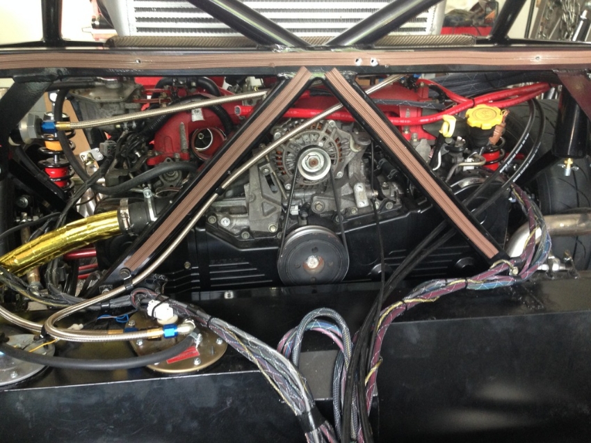
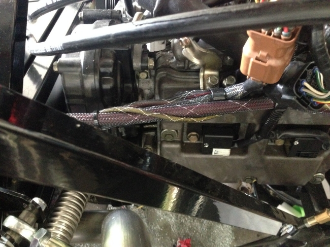
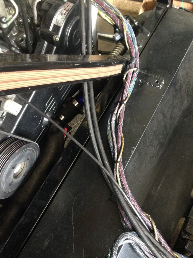
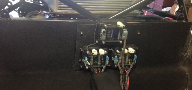
Here are a few pics of my harness I used fire proof sleeving for all my wires. Each main connector has its own sleeving so that I could manage the wires better. I find that having a large clump of wires just makes things harder to manage as well as diag if you ever have any problems. All my wires run into the center tunnel so that the ECU sensitive parts can be protected from heat and water.